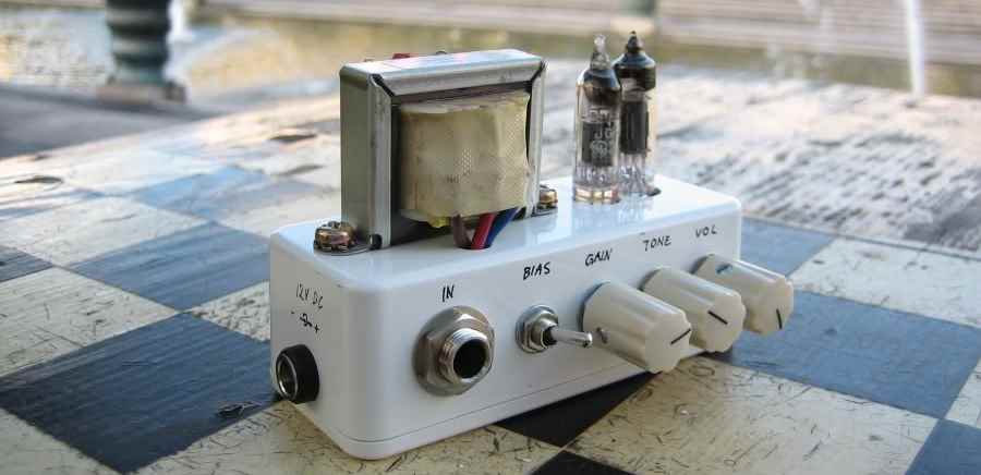
Superfly in a 1590A
Recently I posted some pictures on diystompboxes.com of my Superfly build, people were impressed by the fact that I squeezed it into a 1590A enclosure and I thought the result of my hundreds of hours of planning the build deserved to be posted to the public.Components
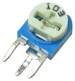
When you're about to squeeze a circuit with (among other things) 8 capacitors, 17 resistors, 1 IC, 2 transistors, three pots, two jacks, two switches and two submini tubes in a 1590A, you'd be wise to think about the size of any and all components. Considering this, the sacrifices I've made in this build are surprisingly few as far as component selection goes. The high voltage electrolytes were changed from 350V to 250V, this took a few millimeters off both the height and width, even then I searched high and low to find the smallest caps possible. Secondly I found that socketing the 555 made it too high, so it's unsocketed. The trimmer pot is the standing type selected for minimum board real estate, and for the fact that it can be adjusted from the side.
Oh, and the pots better be the 9mm kind with the smallest knobs you can find.
Component Placement
If most components are you're average type the placement was given far more consideration (I estimate I spent more than a hundred hours in DIYLC moving things around). Only three out of seventeen resistors lie down. The circuit is divided into two boards, one for the SMPS and one for the amp part, though the reservoir caps are placed on the amp board. The tone stack was moved off board and the 330uF capacitor (on the 12V input) as well. The tone stack was soldered directly to the pots, the 330uF directly on the power jack.The bias switching is slightly changed with the higher value resistor permanently in place and the other resistor (value adjusted) switched in to lower the total resistance to close of the value of the corresponding resistor in the original schematic.
The component numbering follows Ricks Superfly Special layout. Use that layout for component values, except for the bias resistors, I mixed those up. Set R3 to 2K2 or 4K7 and calculate what value R17 should have to give you about 820R in parallel with R3. Also read the note on Ricks layout.
Socket the tubes
I first soldered the tubes directly on the board but later desoldered and fitted sockets (8 pin IC sockets). Not to be able to change tubes, but the thermal coupling of the solder made the components closest to the tubes very hot. I've thought about ways to make a "breakout" board with sockets that should hover just beneath the enclosure top so you can actually switch tubes from the outside. Currently this is impossible or close to, I'll cry like a baby if and when one of my tubes gets dislodged. Some way of securing either that the tubes won't come lose or that you can re-seat them would be nice.Wiring
The wiring follows the standard wiring for the Superfly (except the previously mentioned bias wiring) but has added the standby mod, a switch stopping the 555 from ticking and thus limits the voltage to the plates to 12V instead of 185V. Using this you can let the tubes heat up before putting the full voltage on them, this is said to be kinder to them.
Board connections

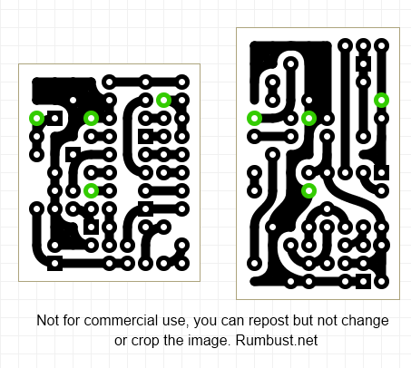
These are the four points where the boards should be connected to each other. Solder long wires to the Amp board and cover them with shrink tubing, as "high" as the components on the SMPS board.

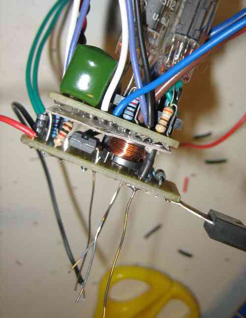
Strip the connectors but leave them long. To make it easier to get them through the holes on the SMPS board cut them to different heights, this way you can thread them one at a time. Don't forget to add something to insulate between the amp board and the components of the SMPS board. I forgot, desoldered four wires in the middle of a cramped board, added a cardboard sheet and resoldered. You can do it this way too, but I don't recommend it.

In this image the mosfet is temporarily soldered flat against the copper side of the SMPS board, this facilitated testing before stuffing everything in the box, yet made it easy to desolder when it was time to put everything in the enclosure. If the mosfet was soldered in place when the boards were mounted in the enclosure there'd be no space to bolt it to the enclosure. As a result the mosfet is bolted to the enclosure first and soldered only after the boards go in.
PCB Transfer
This should (if I'm not completely mistaken) be 300 dpi (click on the thumbnail for full size image). The top left corner of the SMPS board (the right one) will need to be cut so the board fits into the enclosure. In fact, cut close to the traces on all sides.
Box Layout

This image shows three switches, the actual build ended up with just two of them. The third switch were to be a tone bypass but I decided against it mostly because I lacked a DPDT switch.

Tips
- Always select the smallest parts you can find and try hard to find them.
- Measure 42 times drill once.
- When you think you're ready to put everything into the enclosure, think a hundred times more about the order you put things in.
- When you know the order things go inside the box, think a hundred times more about it and this time also think about how each item is wired, the exact path the wire goes, and when and how you'll solder those wires.
- Wait, how many wires did you say you could route beneath that tele jack? Are you really sure they'll fit?
- To the greatest extent possible, test the circuit before a) fitting the boards closely together b) stuffing everything in the box.
All images are Copyright, Per Trelje and may not be used commercially.